
Are you new to this?
Go and see what this is all about
Go to ETSY Store to get this product
Do you like what you see - hit a TIP JAR button below
How to Design a Parametric Leg Frame and Book Shelf in TopSolid Wood (Step-by-Step Tutorial)
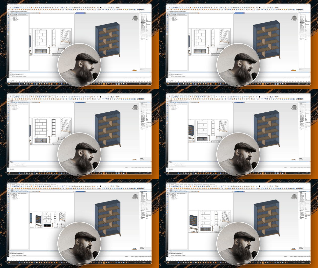
If you build furniture for a living, you already know the real time-saver isn't modeling one piece — it's building a piece once and reusing it forever. In this walkthrough, I take you through my process for designing a fully parametric leg frame in TopSolid Wood, then reuse it to build a complete freestanding bookshelf unit, right through to finished shop drawings ready for cutting.
Here's a breakdown of the workflow, useful whether you're new to parametric modeling or just want to see how another cabinetmaker approaches it.
1. Sketching the Leg Frame Foundation
Every parametric part starts with a driving block — a simple bounding box that defines the overall size limits. From there, I sketch the leg profile on the bottom plane, defining:
- The bottom kick-out dimension (how far the foot flares outward)
- The top attachment dimension where the leg meets the frame
- A basic extrusion connecting the two profile curves into a tapered leg shape
2. Turning Dimensions into Parameters
This is where the real power of parametric design kicks in. Instead of hardcoding dimensions, I create named parameters for every controllable value:
By replacing fixed numbers with parameters, adjusting one value instantly updates the entire leg geometry — a huge advantage over static, one-off models.
3. Mirroring to Build a Full Four-Leg Set
Once the first leg works correctly, I mirror it across two planes to generate all four legs symmetrically, then group them together, assign them to a dedicated layer, and label them clearly (e.g., "Frame Legs") so they're easy to manage inside the assembly tree.
4. Building the Connecting Frame
With the legs in place, I sketch the horizontal frame members that tie the legs together, again driven entirely by parameters:
- Frame thickness
- Frame height
- Shift/offset values for alignment
Every face is trimmed precisely to the correct planes, and I fine-tune shadow gaps and thickness until the proportions feel right — in this case landing on a 25mm frame thickness.
5. Saving the Component as a Reusable Family
Once the leg frame behaves exactly as intended, it gets saved into a project library (in my case, under an "Etsy Store" project folder) as a reusable parametric component — meaning it can be dropped into any future cabinet or table design and instantly adapted to new dimensions.
6. Building the Cabinet Body Around the Frame
With the leg frame saved, I create a new driving block for the cabinet body and insert the leg frame component directly into it. TopSolid automatically prompts for all the saved parameters, so I can either accept the defaults or tweak them on the fly — adjusting leg push-out, panel thickness, and shift values until the leg frame and cabinet carcass fit together without collisions.
7. Adding Panels, Materials, and Finishes
From there, the cabinet gets:
- Overall width, depth, and height dimensions
- Back panel type and inset/overlay settings
- Shadow gap rebates on visible panels
- Material assignments (MDF carcass with an oak veneer finish, painted in a soft blue tone)
- Evenly spaced internal horizontal and vertical dividers using automatic distribution tools
8. Making Components Toggleable (On/Off Parameters)
One of the most useful tricks covered here is creating boolean-style activation parameters — essentially yes/no switches that let you turn features like the leg frame or center divider on or off entirely, without deleting or rebuilding geometry. This is huge for offering design variations (e.g., a version with legs vs. a flush-to-floor version) from a single parametric model.
9. Generating Shop Drawings
Finally, the finished design gets dropped into a drawing template, with:
- Front, section, and detail views laid out on a single page
- X-ray/hidden-line views to show internal frame construction
- Multiple scales (1:10, 1:8, 1:5) used for overview vs. detail views
- Leg-to-carcass connection details pulled out separately for shop reference
The result: a fully dimensioned, print-ready drawing package generated directly from a parametric 3D model — no redrawing from scratch required.
Why Parametric Design Matters for Furniture Makers
The biggest takeaway from this process is reusability. Once a component like a leg frame is properly parameterized, it becomes a permanent tool in your design library — future projects take minutes instead of hours, and design variations (heights, widths, leg styles) become simple parameter edits rather than full rebuilds.
If you're working in TopSolid Wood, SketchUp, or ArchiCAD and want to move toward this kind of workflow, the leg frame example above is a great starting project: small enough to build in an afternoon, but complex enough to teach the core parametric concepts you'll reuse on every future design.
Have questions about parametric modeling for furniture design? Drop a comment below or reach out — happy to help.